

This website uses cookies to improve your experience. We'll assume you're ok with this, but you can opt-out if you wish. Read More
TL;DR: Architectural concrete panel joints should be planned alongside panel dimensions, fixings and adjacent materials from the earliest design stage, not resolved on site. Getting panel layout, joint width and backing details right protects sightlines, shadow lines and handling safety, while early coordination with your concrete specialist avoids costly re-manufacture later.
If you’ve ever watched a beautiful concrete elevation get compromised by an awkward joint running straight through a window mullion, you’ll know that panel layout isn’t an afterthought. It’s a design discipline in its own right, and one that rewards early, deliberate thinking.
How should architects establish a concrete panel layout?
A concrete panel layout is the product of several forces pulling in different directions at once: the architectural geometry you want to express, the practicalities of mould-making, the realities of crane access and transport, and the behaviour of the building frame itself. Get the layout sequencing right early, and every one of those forces works in your favour. Leave it too late, and you’ll be negotiating compromises during fabrication instead of designing them in.
The biggest pitfall we see is architects finalising a façade or feature wall concept before any conversation about panel size, joint position or fixing strategy has taken place. By the time manufacturing constraints surface, structural grid lines, window openings and corner details have often already been fixed, leaving no room to adjust. According to PCI’s guidance on designing with precast, joint widths must accommodate both erection and frame tolerances, and equalising joints around columns can create real problems unless panels can still be adjusted after erection. That single point is worth building your entire layout process around: design in adjustability, because you will need it.
The fix is simple in principle, even if it takes discipline in practice: bring your concrete specialist into the conversation at concept stage, not at construction issue. A layout sketched with manufacturing and handling in mind from day one will always outperform one value-engineered after the fact.
Choosing panel dimensions: appearance, handling weights and mould economics
Panel dimensions sit at the intersection of appearance, structure and logistics, and every decision ripples outward. Larger panels mean fewer joints, cleaner sightlines and a more monolithic read, but they also mean heavier lifts, larger moulds, and tighter coordination with crane capacity and site access. Smaller panels are easier to handle and transport but multiply the number of joints you need to design, detail and align.
PCI’s architectural precast FAQ confirms the general principle: it’s usually more economical to maximise panel size and minimise the number of units, because every erected piece carries its own connection and crane-pick cost. But maximum size is rarely a design choice alone – it’s governed by site access, crane reach, shipping limits and fabrication constraints specific to your region and supplier. Panels wider than roughly 3.6 metres (12 feet) typically require special permits or escorts to transport, and panels longer than around 12 metres may need prestressing to control handling stresses and cracking during transit.
Handling weight deserves the same early attention as appearance. A panel that reads beautifully on an elevation drawing can become a logistical headache if nobody has checked it against the available hoist, the lift lobby dimensions, or the floor loading on an upper storey. Raise these questions with your specialist before dimensions are locked, not after the mould has been cut.
Positioning joints around architectural geometry and design features
Joints are not an interruption to your design; they are part of it. Where a joint lands relative to a corner, a reveal, a window head or a piece of integrated signage either reinforces the architectural intent or undermines it. Positioning joints to align with existing geometry – door heads, floor-to-ceiling transitions, structural grid lines – keeps the finished elevation feeling considered rather than compromised.
This is where precast concrete panel joints earn their keep as a design tool rather than a manufacturing necessity. A joint tucked into a natural break in the geometry disappears into the composition. A joint that cuts arbitrarily across a feature – a brand mark, a piece of lettering, a sculpted relief – draws the eye for all the wrong reasons. The earlier you map your panel breaks against the architectural features you most want to protect, the more control you retain over how the finished work reads.
Joint width, open joints, backing materials and controlled shadow lines
Joint width is a design decision with real technical consequences. Too narrow, and you risk telegraphing cracking or forcing an unrealistic manufacturing tolerance. Too wide, and you lose the crispness that makes a concrete elevation feel precise. For sealed architectural precast, PCI recommends a nominal joint width around 19mm (3/4″), allowing for production and erection tolerances while keeping an effective minimum width that can still be caulked – most sealant suppliers won’t warrant anything narrower than about 10mm (3/8″).
That said, exterior cladding joints and interior feature-wall joints are different animals. Interior architectural GRC work can achieve far tighter, open joints with controlled shadow lines rather than sealants – a detail that depends entirely on precise backing. Open joints with blacked-out backing create crisp shadow gaps between panels, giving a feature wall genuine depth without a visible seal line interrupting the surface. The contrast matters: a 19mm sealed exterior joint and a 3mm open interior shadow gap are solving entirely different problems, and specifying one logic where the other is needed is a common and avoidable error.
Coordinating concealed fixings, structural supports and installation tolerances
Concealed concrete fixings let a panel appear to float, seamless and uninterrupted – but achieving that effect depends on structural coordination happening well before manufacture. PCI’s Designer’s Notebook on connections for architectural precast concrete sets out the range of architectural precast connection types available, and makes a point worth repeating: connections, joints, sealants and facade elements all need to be coordinated for compatibility and for the movement the building will experience over its life. A fixing designed in isolation from the joint strategy around it is a fixing designed to fail.
Panel tolerances deserve the same rigour. Hole-centre markers, cable routes and fixing points can be cast directly into the mould so they align precisely on installation, removing the guesswork – and the on-site drilling – that otherwise creates risk. Tolerances agreed at design stage, rather than discovered during erection, are what keep a feature wall looking as sharp as its first render.
Detailing interfaces with glazing, joinery, flooring and adjacent cladding
Where concrete meets another material, precision matters most and tolerates least. Cladding interfaces between concrete panels and glazing, joinery or adjacent facade systems need the same joint width and fixing logic applied consistently across the boundary, or the junction will read as an afterthought. PCI’s guidance notes that the joint between a precast panel and a window frame should maintain the same nominal width as the panel-to-panel joints around it – a small detail, but one that preserves the rhythm of the whole elevation.
The practical solution is coordination drawings that show concrete, glazing and adjacent cladding together from the outset, not layered on top of each other late in the programme. Precision at these interfaces is what separates a well-executed scheme from one that looks slightly “off” without anyone quite being able to say why.
Morphe Selfridges: nine panels, four wall planes, a mitred corner and 3mm joints
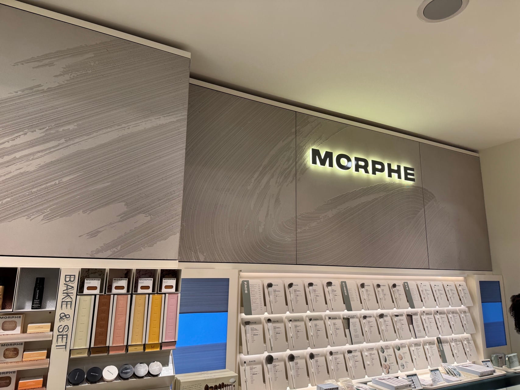
The Morphe Selfridges project brings every one of these principles together on a single, uncompromising brief. Designed by Beyond London for Morphe’s new beauty space at Selfridges, Oxford Street, the scheme called for a sculpted GRC feature wall carrying a flowing brushstroke relief, inspired by Morphe’s own make-up brushes, translated across four separate wall planes.
We formed the artwork across nine bespoke 1200mm-high GRC panels, using polymer mould liners built specifically to reproduce the brushstroke texture with precision. The external corner was detailed as a mitre, so the relief flows continuously around it rather than breaking at the junction – a detail that depends entirely on panels being positioned and jointed with genuine accuracy. Hole-centre markers for the illuminated MORPHE lettering were cast directly into the moulds, so every fixing and cable point aligned exactly on installation. Between the panels, 3mm open joints with blacked-out backing create the crisp shadow lines that give the relief its depth.
The brief changed mid-programme – panel dimensions and the installation date shifted – and the artwork had to be re-mapped and adapted to suit. That’s the reality of bespoke architectural concrete: the layout has to stay flexible enough to absorb change without losing design intent. The panels were installed overnight while Selfridges continued trading, coordinated to cause minimal disruption to the store.
“Our space in Selfridges looks amazing! The concrete has worked so well – it’s beautiful,” says Adrienne Davitt, Head of Visual Merchandising EMEA at Morphe.
Panel set-out and interface approval checklist
PCI’s guidance on envelope tolerances for architectural precast identifies the erection-tolerance failures worth designing out before manufacturing begins. Use this as your interface approval checklist before any panel set-out is signed off:
- No tapered joints – joint width should be consistent top to bottom, not narrowing or widening across the panel height
- No jogs at panel intersections – adjacent panel faces should sit flush at corners and returns
- No non-uniform joint widths across the elevation – inconsistency reads as error, even at a few millimetres
- No out-of-plane offsets between adjacent panels
- Opening dimensions checked against window, door and signage sizes before fabrication, not after
- Connection execution reviewed against the structural support and fixing strategy, not assumed to resolve itself on site
- Mock-ups produced and approved before full production begins
- Manufacturing layout cross-checked against the proposed design layout, with any changes to panel dimensions or programme formally re-approved by the design team
Working through this list at set-out stage – rather than during erection – is what separates a smooth installation from a sequence of site queries nobody has time for.
Your next best action
Panel layout, joint detailing and fixing strategy aren’t separate conversations – they’re one conversation, and the earlier it happens, the more design intent you protect. If you’re approaching tender stage, value engineering a feature wall, or simply want technical input before your concept is finalised, explore more of our concrete wall panel capabilities or speak directly to our team via our contact page. We’ll work with your design team from concept through to installation, protecting the design intent at every stage.
Frequently asked questions
What are the four types of concrete joints?
The four principal planned joint types are control (contraction) joints, expansion joints, construction joints and isolation joints. A control joint is a formed, sawed or tooled groove that creates a weakened plane to regulate where cracking occurs as the concrete shrinks. An expansion joint is a separation between adjacent sections that allows movement from dimensional changes, with some or all reinforcement interrupted. A construction joint is an interface between separate concrete placements, created intentionally to facilitate the build sequence. An isolation joint fully separates adjacent sections, allowing movement in three directions, with all bonded reinforcement interrupted. A related but unplanned fifth category, the cold joint, is a discontinuity caused by a delay in placement long enough to prevent proper bonding between pours – according to the American Concrete Institute, this is treated as a defect rather than a designed joint type.
How wide should a precast concrete panel joint be?
For sealed exterior architectural precast, a nominal joint width of around 19mm (3/4″) is typical, allowing for production and erection tolerances while remaining wide enough to caulk reliably. Interior feature-wall joints using open, unsealed detailing – as seen on projects like Morphe Selfridges – can be far narrower, sometimes as tight as 3mm, because the joint is designed to read as a controlled shadow line rather than a sealed weather joint.
Who should be involved in panel layout decisions, and when?
Panel layout should involve the architect, the concrete specialist and, ideally, the structural engineer from concept stage onward. Decisions on panel dimensions, joint position and fixing strategy made before the design is locked are far cheaper and easier to execute than changes requested once manufacturing has begun.
What’s the difference between a concealed fixing and a standard structural connection?
A concealed fixing is detailed so that no bracket, bolt head or connection hardware is visible on the finished face of the panel, typically achieved by casting fixing points into the panel during manufacture. A structural connection, by contrast, carries the panel’s load path back to the building frame and may be partly or fully exposed, depending on the application. Both need to be coordinated together, since the joint, the fixing and the structural support all interact.